Demystifying VCF 9.1 Networking: From Core Architecture to VPCs and VNAs
If you have ever felt overwhelmed by the networking layer of VMware Cloud Foundation (VCF), you are not alone. In this post I will try to explain how the different components work together in VCF NSX not only for you (the reader) but also for myself 😉
With the release of VCF 9.0 and 9.1, VMware (now Broadcom) has fundamentally changed the game by introducing a public-cloud-like consumption model: the Virtual Private Cloud (VPC).
Let’s break down how VCF networking works today, step-by-step, from the physical hardware up to the modern developer cloud.
1. The Starting Point: NSX Foundation Architecture
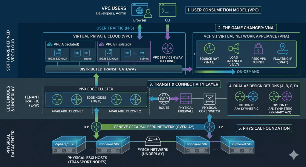
Before we can build multi-site datacenters or deploy containerized apps, we need to understand the software-defined engine running under the hood. NSX relies on a few core components to virtualize hardware:
- Transport Nodes: Physical ESXi hosts prepared with NSX software, enabling them to process virtual network traffic.
- Geneve Encapsulation (Overlay): The magic protocol that packages network traffic from virtual machines. This allows overlay traffic to travel across the physical network (Underlay) without physical switches needing to know about the virtual subnets.
- TEP (Tunnel End Point): A unique IP address assigned to each ESXi host that acts as the gateway for Geneve-encapsulated traffic. Hosts communicate directly from TEP to TEP.
- Segments: The virtual network cables (logical switches) that your VMs plug into.
- Edge Nodes: Dedicated virtual machines (or bare-metal servers) that act as the landing zone for routing and provide the bridge to the physical world (North-South traffic).
Two-Tier Routing
To separate administrative control from developer agility, NSX uses a two-tier routing system:
- Tier-1 Router (T1): The local gateway for specific tenants or workloads. The T1 handles internal east-west traffic and runs distributed across all ESXi hosts simultaneously.
- Tier-0 Router (T0): The border gateway that connects the virtual NSX environment to physical core switches using dynamic routing protocols like BGP for external north-south traffic.
2. Multi-Site Architecture: Designing for Dual Availability Zones
When your VCF environment spans two geographically separated locations (AZ1 and AZ2), you face a critical design choice regarding how your Edge Cluster handles high availability and network isolation.
Model 1: NSX Edge Node HA (Recommended)
Edge Nodes are physically pinned to their respective locations (e.g., two in AZ1 and two in AZ2) and never vMotion across sites. High availability is managed entirely at the NSX software layer.
- Networking: TEP and Uplink VLANs do not need to be stretched across datacenters. Each zone uses its own independent subnets.
- The Verdict: Excellent fault isolation. A network outage or a human error in AZ1 cannot physically impact the network layer of AZ2.
Model 2: vSphere HA Recovery
Edge Nodes run as mobile VMs on a stretched vSAN cluster. If AZ1 experiences a complete blackout, vSphere HA restarts the crashed Edge VMs in AZ2.
- Networking: Requires Management, TEP, and Uplink VLANs to be physically stretched (Layer 2 extension) between both locations.
- The Verdict: Longer failover times (minutes instead of seconds) because VMs must cold-boot. It also lowers fault isolation, as a Layer 2 loop or broadcast storm will immediately impact both datacenters.
3. The BGP Routing Matrix (Options A, B, C, and D)
If you follow the recommended Edge Node HA (Model 1) architecture, you must choose how the Tier-0 gateway peers with your physical firewalls and core switches. The deciding factor is whether your physical network can handle asymmetric routing.
- Option A (Active/Active – Asymmetric): The Tier-0 gateway is active on all Edges across both zones. Traffic can leave via AZ1 and return via AZ2. Requirement: You cannot have traditional stateful firewalls in the path, as they will drop asymmetric packets. This option offers the highest throughput.
- Option B (Active/Active – Symmetric): Tier-0 runs Active/Active, but uses BGP mechanisms (like Local Preference or AS-Path Prepending) to force traffic back through the same zone it left. This is ideal for environments with stateful firewalls requiring maximum bandwidth.
- Option C (Active/Standby – Symmetric): The active Tier-0 gateway lives in the primary zone (AZ1), while the standby gateway rests in AZ2. All North-South traffic passes through AZ1. If AZ1 fails, NSX automatically fails over to AZ2. This is the most predictable, traditional setup.
- Option D (Active/Standby – Scripted/Manual Failover): Identical to Option C, but automatic site failover is disabled or strictly gated via Disaster Recovery scripts. This prevents the network from “flip-flopping” between sites during transient network blips.
4. The Cloud Shift: VPCs and VNAs in VCF 9.0 and 9.1
In VCF 9.x, Broadcom completely shifted the consumption model. Instead of dealing with complex T0/T1 design architectures, users now interact with a public-cloud-style Virtual Private Cloud (VPC). Inside a VPC, developers can autonomously spin up subnets, security groups, and routing policies via simplified Connectivity Profiles.
Connecting a VPC to the Outside World
A VPC has three main ways of interacting with external networks:
- Public Connectivity: Outbound internet or shared services access using centralized Source NAT (SNAT). Internal VPC IPs are masked behind a public IP block.
- Private Connectivity: Direct, isolated East-West communication between VPCs using Private Service Gateways or peering. This traffic stays entirely within the software layer without hitting the physical core switches.
- Inbound Connectivity: Making apps accessible from the outside world using Destination NAT (DNAT) or Floating IPs mapped to specific internal VMs.
The VCF 9.0 Dilemma: Centralized vs. Distributed
In VCF 9.0, architects had to make a tough compromise when designing VPC connectivity:
- Centralized Connectivity Model: All VPCs attach to a central Edge VM. It supports advanced services like automatic SNAT pools, but creates a performance bottleneck because all traffic (even between local VPCs) must traverse that single Edge VM.
- Distributed Model: Routing is offloaded directly to the ESXi hypervisors. It is incredibly fast and scalable, but completely lacks support for NAT or Load Balancing. Administrators are forced to hand out unique, physically routable IP blocks again.
The VCF 9.1 Game Changer: The Virtual Network Appliance (VNA)
VCF 9.1 introduces the Virtual Network Appliance (VNA), completely eliminating this dilemma. A VNA cluster is a lightweight software appliance deployed directly from vCenter that hooks into a Distributed VPC environment.
With VNA, you get the best of both worlds:
- Distributed Routing: Standard network traffic routes directly on the ESXi hosts for ultra-low latency and maximum throughput.
- Advanced Services On-Demand: The moment a developer requests an advanced network service within their distributed VPC—such as Outbound NAT, Flexible DNAT, L4/L7 Load Balancing, or IPsec VPN tunnels—that service is instantly and dynamically spun up on the scalable VNA cluster.
Putting It All Together: The Big Picture
When you connect all these puzzle pieces, the entire modern VCF network chain clicks into place:
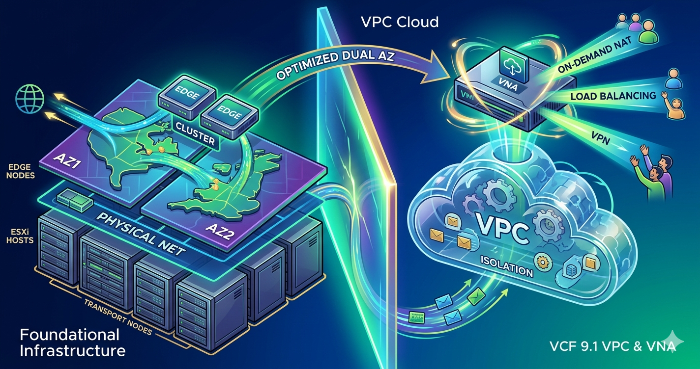
A developer requests a network segment inside their isolated VPC. Thanks to VCF 9.1 and VNA, their application benefits from bare-metal distributed routing speeds while still utilizing enterprise features like NAT and VPN. This traffic travels through the Centralized Connectivity Model straight to the underlying Edge Nodes. Because these Edges are laid out across a Dual Availability Zone (Model 1) using an intentional BGP Routing Option (like Option B or C), data flows symmetrically, securely, and resiliently across physical datacenters.
The complexity is hidden; the performance and reliability remain. Welcome to the future of the private cloud!