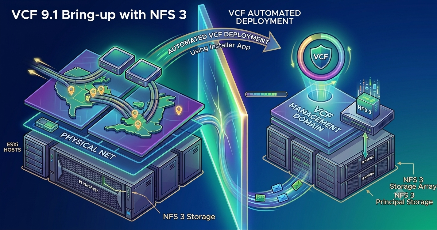
Hands-On Guide: How to install VCF 9.1 on NFS Principal Storage
When setting up VMware Cloud Foundation (VCF) 9.1, the documentation leans heavily toward using vSAN or Fibre Channel for the Management Domain. But for my latest deployment, I went a different route: NFS as Principal Storage. It is a fully supported, highly efficient alternative, but navigating it required a very specific sequence of steps to handle our network design, switch models, and IP constraints.
Here is exactly how I prepared the environment, cleared the pre-validation hurdles, and got the deployment across the finish line.
Step 1: Adopting the Storage Separation Distributed Switch Model
For this deployment, the target architecture relies on the Storage Separation Distributed Switch model. This model is designed to keep management and storage traffic logically and physically distinct across the distributed switches. And for redundancy, both switches utilize two physical network interface cards.
However, a key detail to know about the VCF Installer workflow is that a single physical NIC (pNIC) configuration on the standard switch (vSwitch0) is strictly prescribed for the initial bringup phase.
When you run the VCF Installer, it uses this single active uplink to communicate with the hosts initially. Once the initial automated steps complete, the installer automatically builds the final cluster, deploys the Storage Separation Distributed Switches, maps the remaining uplinks, and migrates the host networking over to the final distributed architecture. You don’t have to manually scale out or add pNICs post-deployment; the installer handles the transition to the final multi-NIC distributed switch model natively as part of the cluster creation.
Step 2: Cleared the Multi-NIC Validation Trap
Because the VCF Installer strictly expects that single-pNIC configuration on vSwitch0 to kick off the deployment, you have to ensure your baseline ESX hosts match this expectation perfectly before you begin. If your hosts have multiple vmnics (your uplinks) connected to the default standard switch, the VCF Installer validation will instantly fail during the ESX Host Configuration check.
As noted in Broadcom KB 415469, the installer throws an error stating it expects only 1 physical NIC. To avoid this roadblock, I logged into the ESXi Host Client of every single host in my inventory before starting and performed these clean-up steps:
- Navigated to Networking > Virtual Switches > vSwitch0.
- Checked the assigned uplinks.
- Found that a secondary uplink (vmnic1) was active alongside vmnic0. I edited the settings and removed the secondary uplink, leaving exactly one physical NIC bound to vSwitch0.
- Saved the settings.
Taking five minutes to do this manually across the hosts ensured the VCF Installer validation passed without a single complaint.
Step 3: Bootstrapping the First Host (Manual NFS Mount)
The VCF Installer automates the cluster build, but when you aren’t using vSAN, it needs an initial landing zone on the primary host to get started. Before kicking off the automated installation, I had to manually mount the NFS datastore on the first ESXi host.
The installer uses this first host to upload initial boot files, OVF templates, and bring up the temporary appliances required to orchestrate the rest of the deployment.
Here is how I did it:
- Connected directly to the ESXi Host Client of my designated first host.
- Went to Storage > New Datastore > NFS.
- NFS Version: Picked the version matching our storage array (NFS v3).
- NFS Server Address: Entered the IP of the storage array.
- Share Directory: Entered the exact export path.
- Named the datastore exactly as I intended to name it in my VCF deployment parameters.
Once this was mounted on Host 1, the VCF Installer detected it and automatically handled mounting it across the remaining hosts in the cluster as it configured the distributed switch environment.
Step 4: The IP Allocation Trick for the First Host
One critical detail when filling out the Planning & Preparation Workbook is how you allocate your NFS IP addresses. In the workbook, you define a specific pool/range of IP addresses that the VCF Installer will use to configure the production NFS vmkernels across all hosts.
Here is the catch: when you manually create the temporary NFS vmkernel adapter on the first host to bootstrap the storage mount (Step 3), you must not use an IP address from that workbook range. If you use an IP from the production range, you will run into an IP conflict or validation failure when the automated installer tries to roll out the cluster configurations. Instead, I used a temporary IP address that was within the same storage subnet, but strictly outside of the range defined in the workbook. This allowed the first host to talk to the NFS array perfectly during the initial phase, leaving the designated workbook range clean and available for the VCF Installer to assign during automated deployment.
The Result
By aligning my prep work with these exact parameters—cleaning up vSwitch0 for the initial bootstrap requirements, bootstrapping Host 1, and using a temporary IP outside the workbook range—the VCF Installer sailed through the validation phase. The automated bringup completed smoothly, automatically transitioning my hosts from the single-pNIC standard switch baseline into a fully realized, multi-NIC Storage Separation Distributed Switch model backed by NFS.