
Building a Stretched VCF Workload Cluster on NFS: Lessons from the Field
VMware Cloud Foundation (VCF) is opinionated software. Most of the time that’s a good thing — it removes a lot of the guesswork from building a private cloud. But the moment your design deviates even slightly from the “textbook” vSAN-based stretched cluster, you start hitting friction points that aren’t well documented. This post walks through building a workload cluster stretched across two data centers where NFS is the principal storage, not vSAN, and the workarounds needed to get there — including some NSX configuration that only becomes necessary once the cluster is live.
The Design
The goal was straightforward on paper:
- One workload domain
- One cluster, with hosts split across two physical data centers (DC1 and DC2)
- NFS as principal storage, shared and reachable from both sites
- NSX-T as the networking layer for the domain
Where it gets interesting is that VCF’s stretched cluster feature is built around vSAN. The wizard, the witness host requirement, the fault-domain logic — all of it assumes vSAN as principal storage. NFS doesn’t have any of that built in, so a “true” stretched cluster, in the VCF sense, isn’t something you can configure. What you end up with instead is a single cluster object in SDDC Manager whose hosts happen to live in two locations, backed by an NFS datastore that both sites can reach. It behaves more like a stretched cluster in practice than in official VCF terminology — there’s no witness appliance, no per-site fault domain configuration, and no automatic failure handling tied to storage. That distinction matters when you’re documenting the design for other admins later: don’t call it a stretched cluster in the VCF sense, because SDDC Manager never treats it as one.
Problem 1: Network Pools Assume One Set of VLANs
The first real obstacle comes during host commissioning. SDDC Manager uses network pools to hand out vMotion and (normally) vSAN IP information to hosts as they’re added to the inventory. A network pool is tied to a single VLAN and subnet per traffic type, and the commissioning wizard expects every host you add to a cluster to draw from the same network pool.
That assumption breaks down immediately in a two-datacenter design. DC1 and DC2 are separate physical locations with their own local VLANs — there’s no shared Layer 2 domain for vMotion between the sites, and DC2 hosts sit on entirely different VLAN IDs than DC1. Try to commission a DC2 host into the same network pool used for DC1, and it simply doesn’t have a route to the assigned VLAN/subnet.
The workaround is to create a second network pool specifically for the DC2 hosts, using their local VLAN and subnet for vMotion. This means:
- Create Network Pool A (DC1) with the DC1 vMotion VLAN/subnet.
- Create Network Pool B (DC2) with the DC2 vMotion VLAN/subnet.
- Commission DC1 hosts against Pool A, DC2 hosts against Pool B.
- Create the cluster using only the DC1 hosts (the ones on Pool A). The initial cluster creation wizard only accepts hosts from a single network pool — you cannot mix pools at this stage.
- Once the cluster exists, add the DC2 hosts (Pool B) as a separate “add host to cluster” operation. That workflow is distinct from initial cluster creation, and it’s the point where a second network pool is actually accepted.
So the real constraint isn’t that a cluster can only ever contain hosts from one pool — it can end up with more than one — it’s that SDDC Manager only enforces “single pool” during the initial creation wizard. Anything added afterwards, through the add-host workflow, can come from a different pool. Plan your build order accordingly: DC1 first as the initial cluster, DC2 second as an add-host step.
Problem 2: Reaching NFS During Bring-Up
The second friction point shows up before the cluster even exists, during cluster creation itself. As part of that workflow, VCF needs to validate that NFS is actually reachable before it will proceed — but at that point the only vmkernel interfaces that exist are whatever imaging created for management traffic, and depending on your network layout the management VLAN has no route to the NFS storage network at all.
Importantly, this check only needs to succeed for the first host added to the cluster. VCF uses that host to validate the NFS export during cluster creation; it doesn’t require every host to independently prove NFS reachability at that stage. So the fix is a temporary vmkernel interface on just that one host:
- On the first host being added to the cluster (via the Host Client or
esxcli), add a vmkernel interface on the port group/VLAN that has a route to the NFS array. - Assign it an IP in the storage subnet.
- Confirm the export is reachable, e.g. with
vmkpingagainst the NFS server’s storage-facing interface, using the correct MTU if jumbo frames are in play. - That’s it — you don’t need to actually mount the datastore. The reachability check is what VCF needs; the real NFS-tagged vmkernel interface and datastore mount get created properly later as part of the standard cluster/network configuration.
There’s a catch worth planning for. Later in the cluster creation workflow, VCF creates the distributed switch(es) and migrates the hosts’ networking onto them, which includes removing the local standard vSwitches and their port groups. If the temporary vmkernel interface is still sitting on a standard vswitch on that first host when this migration runs, the migration can fail to clean up that vswitch — and if it does, the whole cluster creation task fails partway through.
If you hit this: remove the temporary vmkernel interface manually from the host, then retry (restart) the failed cluster creation task in SDDC Manager. It should proceed normally from there. In hindsight, it’s cleaner to remove the temporary vmkernel interface yourself as soon as the NFS reachability check has passed, rather than waiting for the workflow to trip over it.
Problem 3: NSX Configuration After Cluster Creation
Once the cluster exists and both sites’ hosts are prepared as NSX transport nodes, there’s still work to do — because DC2’s networking doesn’t match DC1’s, and the default transport node profile applied during cluster creation is built around a single, uniform network configuration.
Uplink Profile for DC2
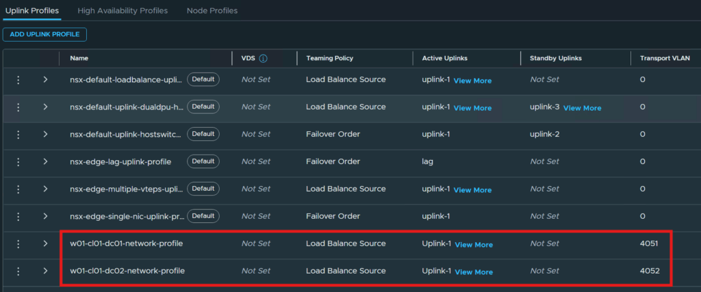
The uplink profile created automatically (or manually, if you’re doing NSX host prep by hand) during initial configuration is scoped to DC1’s VLAN for the NSX overlay (host TEP) traffic. DC2 hosts sit on a different VLAN, so a second uplink profile is needed:
- Same teaming policy and active/standby uplink structure as DC1, to keep behavior consistent.
- Transport VLAN value set to DC2’s TEP VLAN instead of DC1’s.
Sub-Clusters and Sub-Transport Node Profiles
This is the piece that actually makes host-level overrides possible, and it’s built around a specific NSX concept called a sub-cluster. A standard transport node profile is applied at the cluster level and pushes identical configuration — same uplink profile, same IP pool, same teaming — to every host in the cluster. That’s fine when every host is on the same network, but it’s exactly wrong here, so NSX lets you carve a sub-cluster out of the existing cluster and attach a sub-transport node profile to just those hosts. The process has three parts:
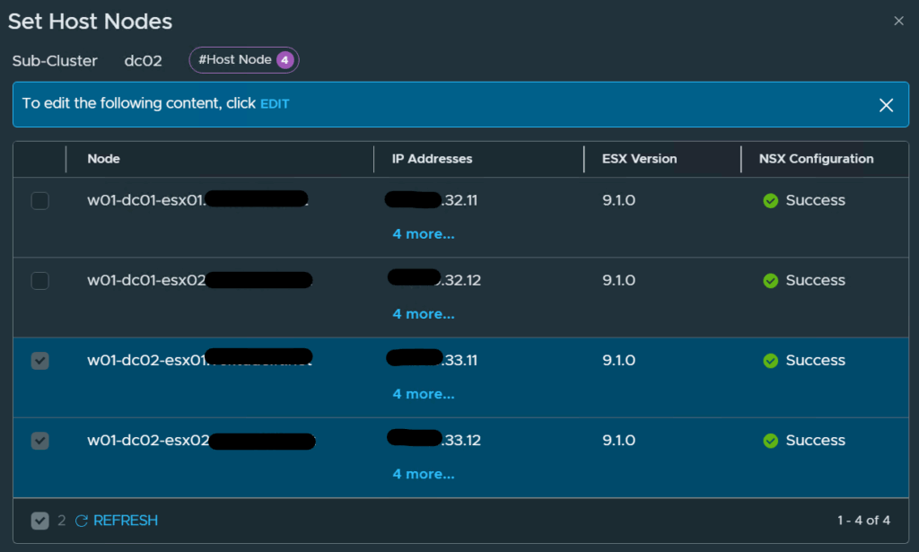
1. Configure the sub-cluster. In NSX Manager, under System > Configuration > Fabric > Hosts > Clusters, select the cluster and set a sub-cluster, giving it a name and adding the DC2 hosts as its nodes. The DC1 hosts stay outside the sub-cluster and continue to be governed by the cluster-level transport node profile.
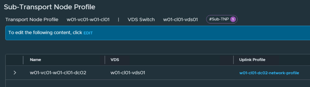
2. Create a sub-transport node profile. When creating (or editing) a transport node profile and configuring its host switch, there’s a “Sub-Transport Node Profile” option. This is where you point DC2 at its own uplink profile and TEP IP pool, distinct from the cluster-level ones used for DC1.
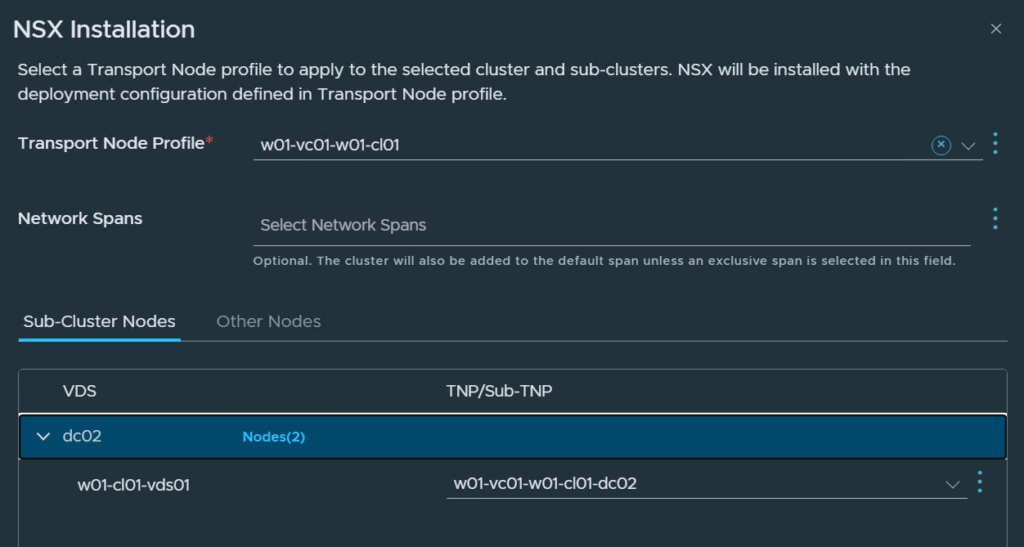
3. Apply the transport node profile to the sub-cluster. From the cluster’s “Configure NSX” screen, select the transport node profile that contains the sub-transport node profile, then expand the sub-cluster entry and assign the DC2-specific sub-transport node profile to it explicitly.
Without this, DC2 hosts either fail host preparation (because they can’t reach a TEP IP pool tied to DC1’s VLAN) or come up with TEP addressing that isn’t actually routable from their local network.
Broadcom has a walkthrough with the exact click-path and screenshots for each of these three steps, which is worth keeping bookmarked: Creating and Configuring NSX Sub Transport Node Profiles on NSX Transport Node Sub Clusters.
IP Pool for DC2 TEP Interfaces
Tied directly to the above: host TEP interfaces need IP addresses out of a pool that’s actually reachable on DC2’s local network. Reusing DC1’s TEP IP pool for DC2 hosts doesn’t work for the same reason the network pool problem existed in the first place — different VLAN, different subnet, no shared broadcast domain.
So a second IP pool is required, scoped to DC2’s TEP VLAN/subnet, and it’s this pool that gets referenced in the DC2-specific sub-transport node profile above. Once that’s in place, DC2 hosts pull TEP addresses from their own local subnet and overlay traffic (Geneve) routes correctly between sites via your physical network’s inter-site routing.
Summary
None of these problems are insurmountable, but none of them are called out clearly in the standard VCF stretched-cluster documentation either — because that documentation assumes vSAN. The pattern across all three issues is the same: VCF’s wizards and default profiles assume network uniformity across a cluster, and a genuinely multi-site design on NFS breaks that assumption in a few specific, findable places:
- Network pools — one pool per site, not per cluster, applied at host commissioning.
- NFS reachability during bring-up — a temporary vmkernel interface to bridge the gap before the cluster and its “real” storage networking exist.
- NSX host preparation — a second uplink profile, a sub-transport node profile, and a dedicated TEP IP pool for the second site.
If you’re planning something similar, the advice is simple: don’t fight the wizard, work around it deliberately, and document each override clearly — because six months from now, “why does this cluster have two uplink profiles” is a question someone (possibly you) will ask.